

above: picture of original SIS Whaddon MK III
a lot more info can be found at : http://uk.groups.yahoo.com/group/sis-whaddon-mkIII/
Here some pictures + a bit comment of my "home brew" attemps:
at 2 May2011,it all started with a posting to the "MK3-Forum"
"Hi to all
sorri for the bandwith but
as newbe , I have some questions:
Is there anybody here on the forum who could give some more information please?
except this forum (many thanks to the contributors of the fb nice pictures and
schematics) the other source of the MKIII is L.Meulstee's "Wireless for theWarrior"(part4)
there is a picture (photograph taken by the Germans in Prague after capture of a Czech agent)
here clearly seen ( displayed on a table) there is a separate TX (upside
down)and AC mains unit in two small wooden boxes
my question
does somebody have more info about the inner part of this type of MK3 TX and PSU
?, maining a picture(s) or photo(s) how all components are situated ?as the only reference I got here at the "files"is a drawing (bmp or pdf ) of Steve KD6VKF
another question
-the dimensions of the frontplate given for this type of TX, are these correct?
-concerning the original article of QST,jan 2008
is there any possibility to receive by mail a scanned version ?
many thanks for helping
best 73's
Josef
on6wj
Steve, KD6VKF and Douglas," fourzoulufive" put me on the right track....mni tnx
now with a lot more info about this little beauty ,time to look around for needed parts and components..
My first MK3 would be some "trial version" to see its behavior ,meaning would it worth to do all the mechanical job ?(lasering/bending steel plate chassis and engraving some paxolin frontplate)
no ....first a more simple way:
making chassis and frontplate with double sided pcboards = much easier way ;-)
START...where to start ?
first problem: need of a square shaped meter resembling a bit to the original,
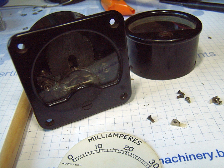
having a "square" meter (+/- good dimensions) , but inside there is a thermocouple ( RF Amps) ,don'want to destroy this rare ,and still working meter,
maybe it's possible to put another moving coil ( from other mA meter) in this house?
pic: dismantled 30mA meter,

"coil" on the back = shunt for 30mA display

second problem: the "body" ( rear) of round shaped meter does not fit into the square housing...some 1 mm to wide in diameter
Time for some lathe job...


with +/- 1 mm less diameter of the backplane, re-installing the moving coil assembly

moving coil "moved" to its new housing, in front :old 30 mA scale,
Thanks to Douglas, 4Z5TO who send me a PDF file with "custom made" scale , PDF printed on "glossy photo paper" ,it took me some time to cut out the good "shape" of the old scale plate, glued at the back of the scale and again some extra time to install the needle stoppers ( thanks Douglas )
checking if after this "hughe renovation / demolition?" , the meter is still functioning....

My first "component" ready for the replica...

Next, making the coils for the tank circuit

The coils will be "plug in" types, the plugs I borrowed from old FT171 Xtals

found some MWcoils


Time to rewind the coilformers on the "cnc" coilwinding machine ;-)

40,80 and 160 meter coils


To keep things simple,te chassis & front are made of double sided pcb,


Time to see if all fits ;
the transformer is an old "Socora" +/- from the sixties,

printed some text on fotopaper and glued with cyanolite glue

on top : some layers of aryllic spray


PA & Aerial Capacitors similar with original


next...


still a lot to do...
Making some "soldertag board" for the 5 x 22 Kohm resistors as seen on picture of original MK3 with...


coming from Henk's (Parasetguy ) "Warehouse" ,

The thickness of the paxolin is just a bit to large for the brass soldertags, so have to souverain the 2,5 mm diameter holes


made one extra spare "board"


...oscillator tankcoil,following mr. David White's schematic + some pictures of innerside of original MK3 set , made this OSC.coil on 1# cardboard former ,+/-60 mm long, wire is double covered cotton


so made a new one , one with less windings
now everything OK
with Xtal Tuning dial +/- half capacity can make light at 160/80 and 40 meter


time to solder some components


Mistery (with the two variable capacitors) solved

At last doing some test to see of Xtal Oscillator is oscillating....
it does !!!


gimmick capacitor between grid and plate
at last: Smoke Test:
(first some test with extra link coupling)


With extra capacity at the AERIAL variablecapacitor =same output
no need for extra link coupling...( so far :test done for 80 meter only )
+/- 6,5 Watt output on 3,5 Mhz
or...290Volt = "sleepingvoltage" for a 807 ;-))


new electrolytes in (old) paper jacket

6,3V doubler for 12V DC antenna relay in new (old ) capacitorhousing


NEW problem:
the antenna coupling-coil is to small
the "ANT variable capacitor" needs extra capacty for 80 and 160 meter for MAX output
solution: making an extra ANT coil inside the former , so for all 3 bands :
max output can be found with only the "ANT variable capacitor "


as the chassis is made of pieces of double side printed board ,the house is made of MDF boards


One of my first "MK3" QSO's made with Alan, G4GEN


The replica will be used during the next weekly UBA QRP Foxhunts "Autumn Edition"


after some corrections made in the "oscillator tank circuit"

my definitive (modern world ) schematic
-provision for QRP or QRO work : via SW3 275VAC or 525VAC are double fased rectified ( in QRO position : Greatzbridge with extra 2x 1N4007)
QRP :PWR = +/- 5 a 6 Watts
QRO: PWR = +/- 20/25 Watts (depending PA is doubling Xtalfreq)
-SW4 is 2 pole switch on front panel,
in ON position : -Xtaloscillator is running via 6V6 -500 Ohm is grounded,
- 6,3V Fil is rectified/doubled ,routed to ANT relay = activated

time to bring back alive my HRO receiver
